

What is Ultrasonic Welding and is it Right for Me?
When investigating ways to join plastic parts, you will almost certainly settle on a process that falls into one of these categories: mechanical, adhesives, or welding. Mechanical processes such as snap-fit, screws, or rivets are great if the product needs to be disassembled during its life or if the product will be run in low volume. Adhesives like glue form a more permanent bond and excel at adhering two dissimilar materials. Plastic welding processes are permanent in nature, have no consumables, and use a combination of heat and pressure to fuse the parts together. One particular welding method should not be overlooked when evaluating manufacturing methods: ultrasonic welding.
What is ultrasonic welding?
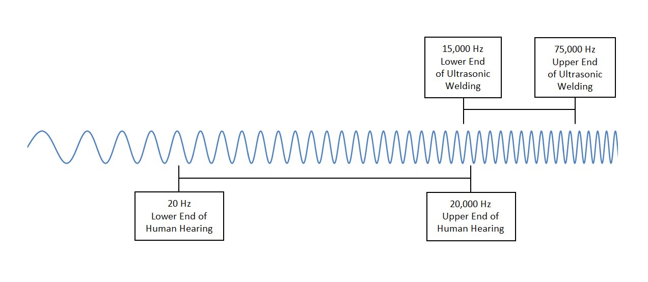
In simple terms, ultrasonic welding uses high frequency vibrations to heat and bond two parts that are touching under pressure. These high frequency vibrations exceed the limit of human hearing in most cases. The range of human hearing is from 20 Hz to 20 kHz while ultrasonic frequencies utilized in these welders typically range from 15 kHz to 75 kHz. The technique was patented in the 60’s and first used in the toy industry. Since then, the technology continues to advance and is used in industries such as medical, electronics, packaging, and automotive. Ultrasonic welding can be used for plastics as well as metals, but this article will primarily focus on plastic welding. To better understand ultrasonic welding let’s examine the components of a welder.
Power Supply. Every ultrasonic welder starts with a power supply. The power supply is sometimes referred to as the frequency generator because it takes standard electrical power (usually 115V) at 60 Hz and converts it to the operating frequency of approximately 20 kHz or 20,000 cycles per second. Other output frequencies commonly available range from 15-70 kHz. This high frequency current is then sent through a special cable to the ultrasonic stack.
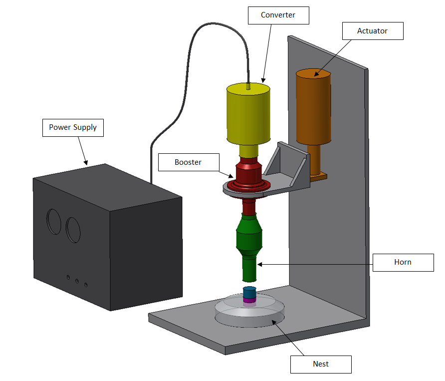
Ultrasonic Stack. The stack is not one thing, but rather the combination of three core components:  the converter, booster, and weld horn. In a plastic welder, the ultrasonic stack is aligned vertically and sits above the parts being welded in a supported column.
Converter. The converter is a piezoelectric transducer which is fed high frequency current from the power supply and outputs mechanical vibrations at the same frequency. The converter works by means of the piezoelectric effect—think quartz watches. In summary, the piezoelectric effect occurs when a mechanical deformation (change in shape due to pressure) occurs to a candidate material which will in turn generate an electric charge. The piezoelectric effect works in reverse also. If an electric field is applied to the material, it will change shape. Piezoelectric transducers found in ultrasonic converters are composed of many piezoelectric ceramic discs, covered on either side by metal plates. These are all stored under pressure in a titanium cylinder. The power supply sends high frequency current to this device, generating rapidly changing electric fields. These rapidly changing electric fields cause a rapid change in the shape of the piezoelectric material, resulting in high frequency vibrations. The titanium cylinder helps to transmit this vibration to the booster.
Booster. The booster is a reactive component to the converter and helps amplify or attenuate the vibration. The vibrations coming from the converter have an approximate amplitude (zero-to-peak) of 8 micrometers (the diameter of a red blood cell). This amplitude must often change to successfully transmit the required energy to the welded joint. The booster increases or decreases
the amplitude of the vibration by a specific ratio. This ratio is determined by the geometry and mass distribution of the booster—each of which are precisely engineered to achieve this ratio. For example, boosters with more mass near the horn decrease the output amplitude. Typical booster ratios are 1:0.6 (decreases amplitude) and 1:2.0 (double amplitude) and are usually made of titanium or aluminum. The ratio can also be expressed as a “gain”, where the gain is equal to the output amplitude divided by the input amplitude. The booster is not the only component of the stack which can change the amplitude of the acoustic waves.
Horn or Sonotrode. The horn is sometimes more commonly referred to as a sonotrode outside the United States. The horn receives vibrations from the booster and further amplifies or attenuates the amplitude of the acoustic waves. The horn is also responsible for applying these vibrations to the parts being welded by direct contact. In a plastic welder, the horn and booster vibrate axially at the operational frequency set by the power supply. The horn contacts the top plastic piece and applies these vibrations perpendicular to the surface of the part. In contrast, metal welder horns lay horizontal, and the vibrations are applied parallel to the parts’ surface. The horn is uniquely engineered to vibrate with its ends moving in opposite directions at all times while the horn’s center stays in place. By multiplying the converter’s output amplitude by the gain of the booster and by the gain of the horn, you can find the stack’s effective output amplitude applied to the part. Titanium is the material of choice for horn construction due to its mechanical properties such as high fatigue strength and hardness, but economical aluminum and steel horns also exist for the right application. There are multitudes of horn shapes that each have their own unique application, and custom horns can be made for special applications. A circular horn for example is useful when the parts are to be welded on their circumference. Before a horn can apply the vibration to the workpiece, it must first be lowered into place.
Actuator. The actuator is responsible for lowering the stack onto the parts to be welded. It must also apply a force consistent with the desired application. Ultrasonic welding actuators are typically pneumatic or electric driven and provide a weld force in the range of 50-750 lbs. Actuators used in metal ultrasonic welder may by driven by hydraulics and see more force. The exact force will be determined based on the design of the parts being welded.
Nest or Anvil. There are typically two parts being welded together—an upper half and a lower half. The lower half sits in a fixture referred to as a nest. The nest will direct the vibrations to the interface between the two parts. When the fixture holding the lower part is more flat, it may be referred to as an anvil. When welding long seams, some machines have a mobile anvil which moves the part along while keeping the welder in place.
The Ultrasonic Welding Process.Now that you know the major components of an ultrasonic welder, it’s time to understand how a typical welding cycle works:
The first step is to load the parts into the nest by hand or by automation—automation is used in high volume runs. Next the controls of the welder will run in one of four modes:
Weld-by-time. Weld-by-time will run the weld sequence for a set amount of time. For years, this has been a standard way to weld. The disadvantage to this process is that it is an open-loop system (no feedback). With the advent of strict quality requirements in industries such as medical, the weld-by-time method cannot always produce the level of consistency required. If one part varies from the next ever so slightly, there is no feedback to account for differences. This results in variations in weld quality and overall part characteristics. With new sensors and advanced controls becoming more accessible, better weld modes have been developed.
Total Energy. One theory for successful welding is that for a given part, there needs to be a certain amount of energy applied to the parts’ interface to produce a satisfactory weld. Total energy mode works by measuring the power consumed by the welder and adjusting the duration of the weld  process to achieve a desired energy input (power x time = energy). This method, while good in theory, is difficult to predict the actual energy applied to the weld due to losses in the machine (ex: energy loss to the fixture).
Collapse (Relative) Distance. Using a linear encoder, the control can measure the distance the horn plunges the top part into the bottom part during a weld. The measurement starts when the horn makes initial contact with the top part (when the actuator lowers) and ends after a preset distance is achieved. This preset distance is a collapse distance—the amount by which the interface between the two parts melt. This method is the preferred method in many situations because you can accurately control the weld depth.
Absolute Distance. When the overall dimensions of the part being welded are critical, the preferred method is “absolute distance”. Using a linear encoder, the welder will continue the weld cycle until a specific overall part dimension is achieved (typically overall height). The total energy, collapse distance, and absolute distance methods all incorporate feedback loops making them closed-loop systems.
After the control mode has been chosen, the actuator depresses the stack. The horn eventually makes contact with the top part and a load is applied. Meanwhile, the power supply provides a current to the converter which outputs a high frequency vibration through the booster and horn. The horn applies this ultrasonic wave to the parts being welded. One of the parts typically have an energy director at the interface. An energy director is a small molded ridge with a height just under 1 millimeter and sides at 60-90 degrees. Due to the vibrations and friction, the energy director will melt and create a molecular bond with the other part’s surface. The weld time usually takes less than a second, after which the weld is quickly cooled due to melting temps staying localized to the parts’ interface. There is no cure time either. Afterwards, the actuator is fully retracted and the parts can be removed by hand or automation.
Best Design Practices.
When evaluating ultrasonic welding as a fabrication method, it is important to keep in mind that some plastics weld better than others.
• Due to their chemistry and thin nature, thermoplastic films and fabrics weld easily with ultrasonic methods.
• Amorphous thermoplastics (such as ABS) are ideal candidates as well.
• Semi-crystalline thermoplastics (such as nylon) prove more difficult, but can be done.
• Thermoplastic elastomers on the other hand are very poor candidates for ultrasonic welding and are generally not recommended.
Different materials have different amplitude ranges necessary for an efficient weld. Most suppliers of ultrasonic welders can supply reference settings for different materials. Welding two different plastics can be achieved if their settings are not too different.
The size of parts are also an important factor. Ultrasonic welding excels with small parts. How big is too big? Well here are some rules of thumb:
• The more difficult the material, the smaller it’s max size can be. Nylon (difficult) can only be about 3.5″, while ABS (easy) can be about 10″.
• Lower frequencies (15 kHz) require larger tools (10″). Higher frequencies (40 kHz) require smaller tools (2.5″)
Part geometry affects the ability to produce clean welds. Ultrasonic welding works well with thin walled parts, long unsupported walls, and internal welds. Complex geometries and deep contours are not well suited for ultrasonic welding.
When designing the interface between the parts, it’s important to add an energy director. An energy director works to concentrate the energy from the horn to initiate a rapid melt. It is typically a triangular profile located on the center of the wall, running the length of the wall. Placing the energy director on the part touching the horn is recommended. A good starting point is an angle of 60-90 degrees with a height equal to 1/8 of the wall thickness. A rule of thumb for the required actuator force is 1 lbf for every linear millimeter of energy director. The design of the parts should include features which help align them. These suggestions are merely a starting point and should be evaluated with an application engineer. A tried-and-true set of empirical data along with established weld procedures are keys to a successful project.
Advantages
Ultrasonic welding provides many advantages over alternative methods:
• High strength welds
• No consumables—no fasteners or adhesives
• Fast—no cure or dry time. Welds in less than a second.
• Easily automated
• Clean and precise
• No ventilation needed
• Can vibrate contaminates out of packaging seals
• Provides tamper-proof hermetic seals
• Low power consumption—works in short bursts
• Great for volatile or heat sensitive products
• Uses standard electrical power (115V @ 60Hz)
• Established technology with many choices in equipment
• Relatively low capital equipment costs
Limitations and Drawbacks.
Here are some limitations to be aware of when evaluating ultrasonic welding:
• Part size must be small
• Geometry must not be too complex
• Limited to certain plastics and combinations of plastics
• Limited weld depth
• May emit audible high pitch noise
When evaluating ways to join plastic parts on your next project, consider the benefits ultrasonic welding can bring you and see if it is right for your application.
Karl Hegna